
Air Quality Control Systems
An integrated, permit-driven air-treatment installation for a co-digestion and gas-upgrading plant.
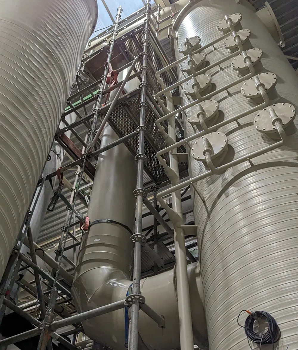
This article describes the design and performance basis of the integrated ventilation and odour-abatement system installed at a biomethane production facility. The facility converts biogas derived from co-digested manure and organic feedstock into grid-quality natural gas, electricity and heat. Because manure reception, anaerobic digestion, ammonia recovery, mechanical separation and thermal drying all release odorous air, a site-wide abatement system is needed to keep emissions within the limits set by the environmental permit. Odorous air is captured from every relevant process area through a two-line ventilation network that segregates high- and low-concentration streams, and is treated in a sequential train of acid scrubbing, caustic scrubbing, humidification and biofiltration. The design achieves an odour-removal efficiency of 85% across the biofilter and upstream chemical scrubber, with a guaranteed minimum of 70%, and its performance is verified continuously against the technical agreement NTA 9065.
01 Introduction
The facility comprises a co-digestion unit combined with a gas-upgrading unit and a combined heat and power (CHP) installation. Feedstock processing and biogas upgrading are conducted within a single large building that houses the manure reception area, the separation system, the ammonia recovery system, the digestate drying area and the product storage facility. All process stages within this building generate exhaust air that carries odorous contaminants at varying loads. The purpose of the system described here is to extract this air, treat it to the required abatement efficiency and discharge it to atmosphere within permit limits.
The application combines two functionally interdependent subsystems: a ventilation system and an odour-control system. The ventilation network defines the air volumes and contaminant loads presented to the abatement train, and the abatement train is dimensioned accordingly. Together they form a single, permit-driven air-treatment installation that operates continuously alongside the production process.
02 Process overview and emission sources
Manure and supplementary feedstock are delivered by truck and discharged inside the building into a concrete reception pit approximately 3 metres deep. A crane feeds two hoppers from which solid and liquid feedstock, wastewater and recycled process water are combined in a mixing installation and pumped to the digesters. Digester effluent is subsequently routed through the ammonia recovery system, which lowers the nitrogen content of the digestate, and then through the separation area, where decanters, grit-removal units and dissolved-air flotation (DAF) units operate. The separated solids are thermally dried, cooled and transferred to storage before being loaded out as dried manure and fertiliser.
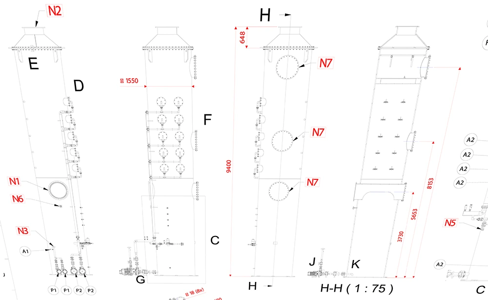
Each stage contributes a characteristic emission. Low-concentration sources include the dried-product storage areas, the dilution buffer and the manure reception area; high-concentration sources include the dryer-condenser vapours, the decanters and the DAF units. To treat these streams efficiently, the design segregates them into two ventilation lines: a low-load line and a high-load line. The high-load line receives additional chemical polishing upstream of the biofilter, whereas the low-load line is routed more directly to the biofilter.
03 Ventilation system
The ventilation system extracts odorous air from distributed points throughout the building and delivers it to the odour-control train. All process areas are maintained under slight negative pressure to prevent fugitive emissions, and the ductwork is likewise held under slight negative pressure. Areas are ventilated crosswise — from side to side and from floor to ceiling — to achieve uniform air exchange. The system comprises extraction points, blowers, ductwork, air grids, dust filters and valves.
The areas and installations that are ventilated include the manure reception area; the dilution buffer; the separation area with its decanters, grit removal and DAF units; the dryer area and dryer condenser; the screw-cooler aspiration and dryer vent air; the bleed air of the ammonia recovery system; the dried-manure storages and expedition area; and the biogas ammonia-removal and desulphurisation unit.
Air flows with a high hydrogen-sulphide (H₂S) content require particular attention to material selection and condensate management, because the resulting condensate can reach a low pH.
04 Odour-control system
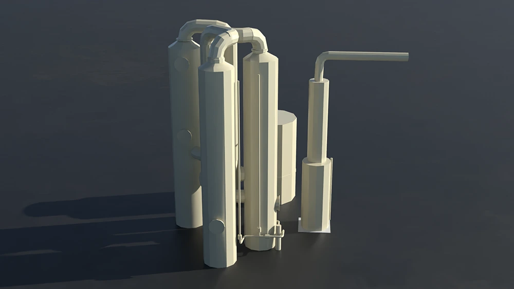
The odour-control train consists of four sequential stages. The high-load stream passes through all four; the low-load stream is directed to the biofilter after humidification. The stages are as follows:
- Acid scrubber — the high-load air is polished chemically using sulphuric acid (H₂SO₄) or nitric acid (HNO₃) dosing to capture ammonia. The reaction product is transferred to the effluent tank as ammonium sulphate or ammonium nitrate.
- Caustic scrubber — a second chemical polishing stage using sodium hydroxide (NaOH), complete with its own dosing and control system. The caustic-scrubber effluent is collected in a dedicated storage tank sized for a minimum of one month of continuous operation.
- Humidifier — conditions the air upstream of the biofilter. It is deliberately constructed so that it can be converted into an additional scrubber, with all flanges and pipe connections provided, should measured odour loads exceed the design assumptions.
- Biofilter / bio-bed — the final biological abatement stage. It is designed for straightforward replacement of filter material and safe access to nozzles and pumps, and is preferably multi-chambered to provide redundancy and allow continued operation during media replacement.
05 Performance and monitoring requirements
The installation is sized with a minimum of 10% overcapacity. The combined biofilter and upstream chemical scrubber achieve a target odour-removal efficiency of 85% and remain above 70% at all times.
Performance is confirmed through independent verification. Within six months of commissioning, an odour study combining emission measurements and dispersion calculations is conducted under representative operating conditions. During the first year of production, the odour emission and removal efficiency of the biofilter with its upstream chemical scrubber, and of the nitrogen-recovery stripping tower, are measured at least quarterly by an independent agency in accordance with the current edition of the technical agreement NTA 9065. The system includes sufficient sampling points, and operation is governed by an odour-control plan that defines the Emission Relevant Parameters (ERPs), their monitoring frequencies, permissible bandwidths and reporting methods.
06 Materials and control philosophy
Materials are selected for a design working life exceeding 15 years and comply with the relevant regulations and Best Available Techniques (BAT), together with applicable European directives including the Pressure Equipment Directive (2014/68/EU), the ATEX explosion-safety framework and the Machinery Directive (2006/42/EC). Particular care is taken in streams carrying high H₂S concentrations, where acidic condensate can develop. The control system operates as a standalone unit while reporting system status and fluid levels to the plant's central HMI via Profibus; the local control cabinet is installed adjacent to the system, and all cabling is labelled.
The installation is integrated with the surrounding civil and process works through clearly demarcated interfaces. The building structure, roof and cladding, together with the foundation slab for the scrubbers and bio-bed, form the civil boundary, while defined flanges connect the abatement train to the NaOH and acid silos, the decanters, the DAF units and the effluent lagoon. The caustic-scrubber effluent is collected in a dedicated storage tank, water is distributed from a single supply connection to the individual installation parts, and all air inlets and grids form part of the ventilation network. Provision for spare parts, the first fill of biofilter media, and a maintenance schedule with a list of consumables support reliable long-term operation.
07 Conclusion
The installation illustrates a complete, permit-driven air-treatment application for a biomethane production facility. Odorous air is captured from every relevant process area — manure handling, anaerobic digestion, ammonia recovery, mechanical separation and thermal drying — and segregated into high- and low-load streams. The high-load stream is polished through acid and caustic scrubbers, all streams are conditioned in a humidifier, and final abatement is achieved on a multi-chambered biofilter. The integrated design, combined with continuous ERP-based monitoring and periodic NTA 9065 verification, keeps odour emissions within the legal limits throughout the service life of the plant.
Frequently asked questions
What odour-removal efficiency does the system achieve?
The combined biofilter and upstream chemical scrubber are designed for a target odour-removal efficiency of 85%, with a guaranteed minimum of 70% at all times. The installation also carries at least 10% overcapacity.
Why is the ventilation split into two lines?
Emission sources differ widely in odour load. Segregating them into a low-load line and a high-load line lets each stream receive only the treatment it needs: the high-load line gets additional acid and caustic scrubbing upstream of the biofilter, while the low-load line is routed more directly to the biofilter after humidification. This keeps the abatement train efficient and correctly dimensioned.
Which treatment stages does the odour-control train use?
Four sequential stages: an acid scrubber (ammonia capture with H₂SO₄ or HNO₃), a caustic scrubber (NaOH), a humidifier that conditions the air and can be converted into an extra scrubber if needed, and finally a multi-chambered biofilter for biological abatement.
How is performance verified over time?
An odour study combining emission measurements and dispersion calculations is carried out within six months of commissioning. During the first year, an independent agency measures odour emission and removal efficiency at least quarterly, in accordance with the current edition of NTA 9065. Ongoing operation is governed by an odour-control plan that tracks the Emission Relevant Parameters (ERPs).
How are streams with high hydrogen-sulphide (H₂S) content handled?
High-H₂S air flows produce condensate that can reach a low pH, so they require careful material selection and dedicated condensate management. Materials are chosen for a design working life exceeding 15 years and comply with BAT and the relevant European directives.
Which standards and directives apply to the installation?
Performance is verified against the technical agreement NTA 9065. The equipment complies with Best Available Techniques (BAT) and applicable European directives, including the Pressure Equipment Directive (2014/68/EU), the ATEX explosion-safety framework and the Machinery Directive (2006/42/EC).
Standards & directives referenced: NTA 9065 · Best Available Techniques (BAT) · Pressure Equipment Directive 2014/68/EU · ATEX · Machinery Directive 2006/42/EC